Categories
Blog

What is CNC machining?

What is CNC machining?

CNC machining is exponentially controlled machining, a method that uses digital information to control mechanical motion and machining processes. Traditional machining is done by ordinary machine tools operated manually. During processing, mechanical tools are used to cut metal by hand, and tools are used to measure the accuracy of products using a calibrator. However, traditional manual processing is far from meeting production requirements.
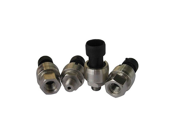
What is CNC machining

The CNC processing quality is stable, the surface texture of the finished product is clear, the metal texture is firm, smooth and smooth, without scratches and edges, and the heat dissipation coefficient of the raw material has little resistance. It will not change with precision machining. Manufacturers can adjust specific processes to improve their heat dissipation performance. For example, oxidation, stretching, cooking, sand blasting and other processes can be performed under numerical control operations.

CNC processing adopts imported equipment; the products processed by the automatic lathe parts are processed with accurate thread, no slip, tolerance up to 0.01 mm, smooth appearance, no burrs and sticky hands. CNC machining is carried out in strict accordance with the size specifications of drawings and samples. The tolerance accuracy is up to 0.01 mm. Each batch of products can be delivered to customers after 3 accuracy tests. The defective rate is strictly controlled within 1/1000.

The CNC machining center automatic control system can usually control the CNC lathe to complete the automatic start and stop, commutation and speed change of the spindle bearing according to the digital program flow instructions. It can intelligently control the feed speed, direction and production processing distance for production processing. Select the size of the CNC blade and change the cutting amount and walking path to complete various auxiliary actions required for production and processing.

The structure of CNC machining CNC lathe also includes spindle bearing box, tool holder, feed transmission device, machine tool itself, hydraulic transmission system, refrigeration system, lubrication system and other parts. It is just that the feed system of CNC lathe and the feed system of horizontal lathe are essentially different in structure type. The composition diagram of the mechanical structure of a typical CNC lathe is the same.

CNC machining is the process that the control system sends out instructions to make the cutter make various movements that meet the requirements. The technical requirements such as the shape and size of the workpiece and the requirements of the processing technology are expressed in the form of numbers and letters. The quality of CNC processing is stable, the surface texture of the finished product is clear, the metal texture is firm, smooth and flat, without scratches and edges, and the raw material has a small coefficient of heat resistance and will not change with CNC processing. Manufacturers can adjust specific processes to improve their thermal performance. For example, oxidation, stretching, cooking, sand blasting and other processes can be performed under numerical control operations.

In the case of multi-variety and small batch production, CNC machining quality is stable and production efficiency is high, which can reduce the time for production preparation, machine tool adjustment and process inspection, and reduce the cutting time due to the use of the optimal cutting amount. It can process complex profiles that are difficult to process with traditional methods, and can even process some unobservable processed parts.

The above explanation is about CNC processing. I hope it will be helpful to you after reading it. If you want to know more about CNC processing, please feel free to consult customer service online or call our service hotline (upper right corner of the website). Consultation, we will wholeheartedly provide you with quality service!

Categories
Blog

Reasons why CNC machining is widely used

Reasons why China CNC machining is widely used

China CNC machining is to use the automatic control system to install digital program flow commands to control the automatic start and stop, commutation and speed change of China CNC machine tool bearings. You can choose a CNC blade, you can change the cutting amount and walking path of the CNC blade, and complete various auxiliary actions required for life-long processing. CNC machining can greatly reduce the total number of tooling and produce parts with complicated processing methods, only the process flow needs to be changed. CNC machining is relatively stable and will not cause machining deviations.

china-cnc-machining

CNC machining can produce complex aluminum parts, and even produce processed parts. Moreover, it can produce a variety of varieties, with high production efficiency, saving labor costs, and at the same time it can realize a variety of mass production. The CNC machining control system can use the control codes or other symbolic instruction rules to logically process the program, use the computer to decode the program, and then move the machine tool and machining parts. After cutting the tool, the blank is processed into semi-finished parts, etc. CNC cutting is not only a more reasonable processing method, but also a common process for aluminum alloy precision machining. Select vertical milling cutter, helical interpolation and contour cutting interpolation with multi-directional cutting function, select fewer tools to process a small number of holes.

In the CNC processing process, we must master the processing skills of craft paint. Choose a reasonable amount of cutting, and personnel choose the cutting speed according to the requirements of the processing material, hardness, cutting conditions, material type, cutting depth, etc. These conditions are necessary to reduce machine wear. Choosing the right tool Generally speaking, when using rough turning, it is best to choose a high-strength tool to better meet the requirements of rough turning. Choosing reasonable fixture parts should fully meet the needs of the machine to reduce unnecessary positioning errors, and thus select special fixtures to accommodate items. Acknowledge a reasonable process. Shorten the processing stroke as much as possible to reduce machine wear.

In CNC machining, system programs usually directly implement specific automatic speed control functions. In this way, the acceleration and deceleration characteristics of the system should be changed, or the CNC program should be modified by the addition and subtraction control, so that ordinary users cannot make the CNC machine tool have the best acceleration and deceleration performance according to their own wishes. Therefore, the flexible acceleration and deceleration control method we proposed adopts the database principle, divides acceleration and deceleration control into acceleration and deceleration description and execution, and separates the acceleration and deceleration description from the system program. In the numerical control system software, a general control channel independent of the acceleration and deceleration database is designed, which can independently complete the acceleration and deceleration calculation and trajectory control.

The above explanation is the reason why CNC machining is widely used. I hope it will be helpful to you after reading it. If you want to learn more about CNC machining, please contact customer service online or call our service hotline ( The upper right corner of the website) for consultation, we will wholeheartedly provide you with quality service!
Categories
Blog

What are the requirements of CNC parts processing technology?

What are the requirements of CNC parts processing technology?

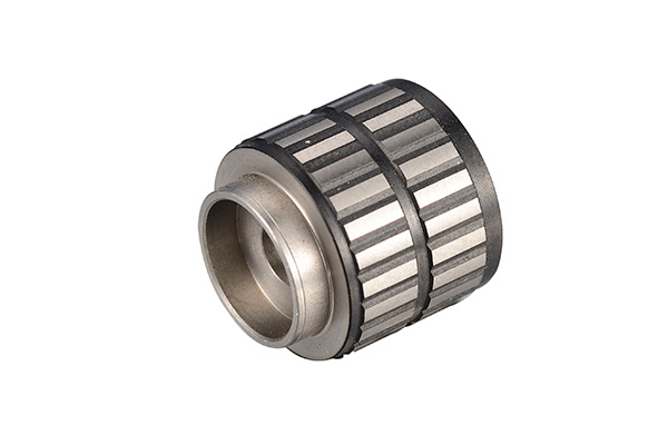
The rotation speed, feed speed and cutting speed of the spindle of the CNC part machining center are mainly determined by the tool, and the setting amount of different tool parameters for processing the same material is also different. However, the tool will provide the parameters set at the time of purchase. For example, different imported tools provide parameters for processing different materials, such as maximum feed rate, cutting volume, and cutting speed.

cnc-parts-processing

Cutting speed, feed speed and cutting depth are the three elements of CNC parts machining cutting conditions, which directly lead to tool damage. As the cutting speed increases, the temperature of the cutter head will increase, resulting in mechanical, chemical, and thermal wear. If the cutting speed is increased by 20%, the tool life will be reduced by 1/2. The relationship between the feed conditions for CNC part machining and the wear on the back of the tool occurs within a very small range. However, the feed rate is high, the cutting temperature increases, and the rear wear is large. Its impact on the tool is less than the cutting speed. The influence of cutting depth on the tool is not as great as the cutting speed and feed, but when the cutting depth is small, a hardened layer will be formed on the material being cut, which will also affect the service life of the tool.

During the machining of CNC parts, the cutting speed needs to be selected according to the material to be processed, hardness, cutting state, material type, feed rate, cutting depth, etc. The selection of suitable processing conditions is based on these factors. Regular and stable wear is the ideal condition to achieve longevity. CNC parts processing requires reasonable selection of fixtures. The parts should fully meet the needs of the machine to reduce unnecessary positioning errors, so select special fixture clamping tools. The processing route is the movement path and direction of the tool relative to the part during the processing of the index-controlled machine tool. It should be able to ensure the machining accuracy and surface roughness requirements, and the machining route should be shortened as much as possible to reduce the tool empty travel time.

When CNC parts are processed for face milling, non-reground carbide end mills or end mills should be selected. In general milling, try to use two passes. The first pass is preferably rough milling with an end mill and continuous passes along the workpiece surface. End mills and end mills with carbide inserts are mainly used for machining bosses, grooves and box opening surfaces. Round knives and round knives (also known as round head knives) are commonly used for machining curved surfaces and variable bevel profiles. However, ball cutters are mainly used for semi-finishing and finishing. Before CNC parts are processed, the processing route should be determined for the waist. Shorten the processing route as much as possible to reduce machine wear.

The above explains the requirements of CNC parts processing technology. I hope it will be helpful to you after reading. If you want to learn more about CNC parts processing, please feel free to consult customer service online or call our service hotline ( The upper right corner of the website) for consultation, we will wholeheartedly provide you with quality service!
Categories
Blog

What are the reasons for errors in CNC machining parts

What are the reasons for errors in CNC machining parts

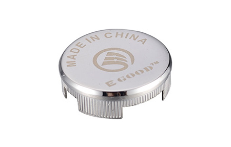
During the operation of the CNC machining parts center, there is a certain gap between the screw and the nut. As the operating time of the equipment increases, the gap gradually increases due to wear. Therefore, the corresponding gap compensation of the reverse movement is the main factor to overcome the shoulders generated on the machining surface. The gap measurement usually uses the dial gauge measurement method, which requires error control. However, it should be noted that the gauge base and the gauge rod should not extend too high or too long, because during the measurement process, due to the long cantilever, the gauge base will be moved by force, resulting in inaccurate counting and compensation values. error.

cnc-machining-parts

Improper tool selection in CNC machining can also cause dimensional errors. During the cutting process, the tool removes material through the main cutting edge. However, after the arc passes through the quadrant and the arc is tangent to the second cutting edge of the tool, the second cutting edge may participate in cutting. Therefore, when selecting or grinding a tool, the wedge angle of the tool must be carefully considered.

During CNC machining, if the machining allowance is not uniform, an error may occur. In the process of achieving part design performance, whether the machining allowance of the CNC machining surface is even or not is also an important reason for whether the molding surface can meet the design requirements. Because the machining allowance is not uniform, it is easy to cause "remapping" errors. Therefore, for parts with high surface shape requirements, the manufacturing allowance should be as uniform as possible before forming, or multiple contours should be processed to meet the design requirements.

CNC machining has clear regulations on the workshop environment, and the heat source needs to be reduced: the focus is on the spindle bearing speed, clearance adjustment and reasonable preload. For thrust bearings and tapered roller bearings, due to their poor working conditions and high heat generation, thrust angular contact ball bearings can be used when necessary to minimize friction and heat generation of certain parts. CNC machining also requires heat insulation: keep the heat source away from the spindle, such as isolating the motor and transmission, using separate transmission, etc. CNC machining also needs heat dissipation: strengthen lubrication and cooling, and use oil cooling, air cooling and other methods to speed up heat dissipation. Reducing the influence of thermal deformation: No matter which method is adopted, it can only reduce thermal deformation, and it is difficult to completely eliminate thermal deformation. Therefore, measures should also be taken to reduce the effects of thermal deformation.

The above explanation is the reason for the error of CNC machining parts. I hope it will be helpful to you after reading. If you want to learn more about CNC machining parts, please contact customer service online or call our service hotline (Upper right corner of the website) For consultation, we will provide you with quality service wholeheartedly!

Categories
Blog

Designing plastic molds involves three steps

Designing plastic molds involves three steps

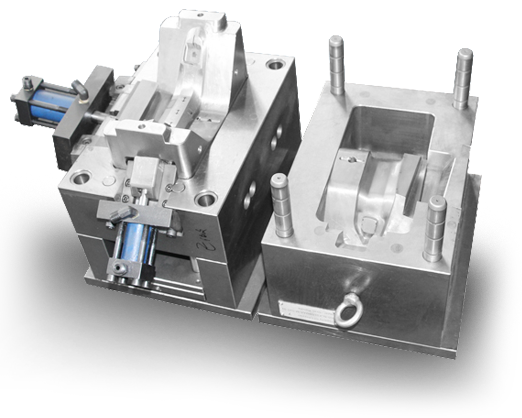
The design of plastic molding dies requires a preliminary analysis of requirements and multiple content discussions. If the demand analysis is not accurate in the early stage, it will directly affect the quality of mold design. Therefore, the design process of plastic molding dies must be standardized and improved. The design is summarized in the following three stages.

Designing plastic molds

First, the exploration stage

This stage is mainly the preparation stage of the design work, comprehensively grasp the plastic parts drawings and technical requirements provided, collect relevant technical data, and explore technical measures to meet the requirements. If necessary, make necessary modifications to plastic parts or technical requirements.

Second, the idea phase

This stage is to propose design concepts for the main parts of the mold according to the requirements grasped in the previous stage and related technical data collected and specialized technical measures, and to study how the design of the main parts of the mold is suitable for the existing processing equipment And technology, and how to ensure the quality of mold processing, speed up the molding speed and improve economic efficiency.

Third, the design phase

This stage is mainly the implementation of the completed idea. The general assembly drawing and parts drawings of the plastic molding mold are given, and the standard parts, remodeling standard parts and mold material plans to be used are proposed.

Categories
Blog

If these problems occur in CNC machining, how to deal with them?

I encountered some abnormal conditions during the CNC processing. If I should deal with it, now I will share it with everyone ~~

If these problems occur in CNC machining

First, the workpiece is overcut:

the reason:
1, the knife, the strength of the tool is not too long or too small. Causes the tool to bounce.
2. Improper operation by the operator.
3. Uneven cutting allowance. (Eg: 0.5 on the side of the surface and 0.15 on the bottom)
4. Improper cutting parameters (such as too large tolerance, too fast SF setting, etc.).
improve:
1. Use the knife principle: it can be big or small, short or long.
2. Add a clearing angle program, the remaining amount should be as uniform as possible, (the remaining amount on the side and the bottom should be consistent).
3. Reasonably adjust the cutting parameters and round the corners with large margins.
4. Using the SF function of the machine tool, the operator fine-tunes the speed to achieve the best cutting effect.

Two points:
the reason:
1. The operator is inaccurate during manual operation and the manual operation is incorrect.
2. There are burrs around the mold.
3, the sub-rod is magnetic.
4. The four sides of the mold are not vertical.
improve:
1. Manual operation should be carefully checked repeatedly, and the division should be at the same point and the same height.
2. Use a stone or file to remove the burr around the mold, and then wipe it clean with a rag. Finally, confirm by hand.
3. Demagnetize the centrifugal rod before dividing the mold. (Ceramic centrifugal rod or other can be used).
4. Calibrate and check whether the four sides of the mold are vertical. (The verticality error needs to be reviewed with the fitter).
Three. Knife:
the reason:
1. The operator is inaccurate during manual operation and the manual operation is incorrect.
2. The tool is incorrectly clamped.
3. The blade on the flying knife is wrong (the flying knife itself has a certain error).
4. There is an error between R knife, flat bottom knife and flying knife.
improve:
1. Manual operation should be carefully checked repeatedly, and the knife setting should be at the same point as much as possible.
2. When the tool is clamped, use a blow gun to clean it or wipe it with a rag.
3. A blade can be used when the blade on the flying knife needs to measure the shank and the bottom surface.
4. Separate a tool setting procedure to avoid errors between R knife and flat knife.
D. Collider-Programming:
the reason:
1. The safety height is insufficient or not set (the knife or chuck hits the workpiece when rapid feed G00).
2. The tool on the program list is incorrectly written with the actual program tool.
3. The tool length (edge ​​length) on the program list and the actual machining depth are incorrectly written.
4. The depth Z axis access number and the actual Z axis access number on the program list are incorrectly written.
5. The coordinates are set incorrectly during programming.
improve:
1. Accurate measurement of the height of the workpiece also ensures that the safe height is above the workpiece.
2. The tool on the program list must be consistent with the actual program tool (as far as possible, use the automatic program list or the picture to show the program list).
3. Measure the actual depth of machining on the workpiece, write clearly the tool length and blade length on the program sheet (generally the tool holder length is 2-3MM higher than the workpiece, and the blade edge avoidance is 0.5-1.0MM).
4. Take the actual Z-axis number on the workpiece and write it clearly on the program list. (This operation is generally written manually and checked repeatedly).

V. Collider-Operator:
the reason:
1. Wrong Z axis tool setting.
2. The number of hits and the number of operations are incorrect (such as: single-sided access without a radius of infeed, etc.).
3. Use the wrong knife (such as D4 knife and D10 knife for processing).
4. The program goes wrong (eg A7.NC goes A9.NC).
5. The handwheel is shaken in the wrong direction during manual operation.
6. Press the wrong direction during manual rapid feed (for example: -X press + X).
improve:
1, the depth Z axis tool setting must pay attention to where the tool setting is. (Bottom, top, analysis, etc.).
2. Repeat the check after the number of hits and operations are completed.
3, when clamping the tool, repeatedly check with the program list and the program before loading.
4. The program should go in order one by one.
5. In manual operation, the operator should strengthen the proficiency of the machine tool himself.
6. In the manual rapid movement, the Z axis can be raised above the workpiece to move.

Six. Surface accuracy:
the reason:
1. The cutting parameters are unreasonable, and the surface of the workpiece surface is rough.
2. The cutting edge of the tool is not sharp.
3, the tool clamping is too long, the blade edge is too long.
4, chip removal, air blowing, oil flushing is not good.
5. Program the cutting method, (you can consider walking milling as far as possible).
6. The workpiece has burrs.
improve:
1. Cutting parameters, tolerances, allowances, and speed feed settings should be reasonable.
2. The cutter requires the operator to check from time to time and change it from time to time.
3. The operator is required to clamp as short as possible when clamping the tool, and the blade should not be too long to avoid emptying.
4. For the cutting of flat knife, R knife, round nose knife, the speed feed setting should be reasonable.
5. The workpiece has burrs: it is directly related to our machine tools, cutting tools, and cutting methods. So we need to understand the performance of the machine tool, and make up for the burr.

Categories
Blog

Programming tips in CNC machining of aluminum products

Programming tips in CNC machining of aluminum products

Programming is an indispensable step in the CNC machining of aluminum products, but many novices do not understand CNC machining programming. When programming and operating machining, it is necessary to avoid collisions in the CNC machining center. Next, I will share some tips about programming in CNC machining.

CNC machining of aluminum products

1.Using computer simulation software
With the development of electronic information technology and the continuous development of classroom teaching of CNC lathe machining, there are more and more software for CNC lathe machining simulation system, and its role is increasingly perfect. Therefore, it can be used to basically check the data and observe the fitness movement of the cutter to determine whether there is a collision.

2.Using the built-in simulation of CNC machining center to display the role of information
Generally, the excellent CNC machining centers often have the function of graphic display information. After entering the program flow, you can enable the graphical simulation to display the effect of the information, and observe the trajectory of the tool in detail to facilitate checking whether the tool will collide with the workpiece or fixture.

3. Utilize the empty operation function of CNC machining center
The accuracy of the trajectory of the infeed can be checked by using the dry operation function of the CNC machining center. After the program flow is entered into the CNC machining center, the tool or workpiece can be mounted, and then the empty operation button is pressed. At this time, the spindle bearing does not rotate, and the operating table starts automatically in strict accordance with the movement trajectory. Collision with the workpiece or fixture. However, under such circumstances, it must be ensured that the tool cannot be installed when a workpiece is provided; when the tool is installed, the workpiece cannot be installed, otherwise collision will occur.

4.Using the locking effect of CNC machining center
General CNC machining centers have a locking function (full lock or double shaft lock). When the program flow is entered, the Z axis is locked, and it can be distinguished whether a collision will occur based on the plane coordinates of the Z axis. The use of this effect should be bypassed by tool change or other operations, otherwise the program flow cannot be based.

5.The setting of plane coordinates and cutter compensation must be appropriate
When starting the CNC machining center, be sure to set the CNC machining center machine coordinate system. The plane coordinates of the CNC machining center should be consistent with the programming, especially in the Z axis orientation. If the error occurs, the probability of the collision between the turning tool and the workpiece is very large. In addition, the tool length compensation must be set appropriately. Otherwise, if it is not empty production processing, or if there is a collision.

6.Improve programming methods
Programming is a particularly important stage for CNC lathe machining. The improved programming method can prevent some unnecessary collisions at a very large level.

All in all, grasping the programming method of cnc machining center can improve the efficiency and quality of production and processing as soon as possible, and prevent unnecessary errors in production and processing. This requires the beginners of CNC machining centers to continue to learn from the actual experience and continuously improve, so as to further strengthen the programming and production capabilities. If as a beginner this level is not very mastery, we should learn more and train more professional and technical personnel with rich experience.

Categories
Blog

What are the steps in the mold processing process?

What are the steps in the mold processing process?

The mold processing process is from cutting to processing and finishing. Established is a hardware and plastic mold manufacturer. I will share it with you and hope to help you.

mold processing process

Cutting material: front mold material, rear mold material, insert material, row material, inclined top material;

Open frame: front mold frame, rear mold frame;
Thickening: the front mold core is thick, the rear mold core is thick, and the parting line is thick;
Copper males: front male copper males, rear male copper males, and parting line milling copper males;
Line cutting: insert parting line, copper male, inclined top pillow;
Computer gong: fine gong parting line, fine gong mold core;
Spark discharge: rough front mold, copper male, male mold wire surface milling, rear mold bone position, pillow position;
Punching, pin eye, die thimble;
Row position, row position pressure pole;

Inclined top

Compound mold thimble, equipped with mold thimble;
Others: ① Tsui Tsui, die pits, waste nails (limit switch nails); ② flying molds; ③ water parts, braces, elastic yellow, and water;
Provincial mold, grinding and polishing, front mold, rear mold bone position;
Fine water structure, support rod screw hook, elastic yellow
Heat treatment, surface nitriding;
Repair printing.

Expertise in stamping dies

Design basis
Specification accuracy The accuracy of the specification between the two.
According to the actual requirements and functions of all the products of plastic products, it is clear which type of external quality and actual specifications belong to:
Plastic products with high appearance quality requirements and low specification accuracy requirements, such as small toys;
Versatile plastic products with strict specifications;
The appearance and specifications are strictly plastic products, such as digital cameras.
Is the die tilt effective?
The inclination of the ejection is related to the ejection and quality of the plastic product, which is related to the entire process of the injection.
There is sufficient inclination of the die;
The inclination should be integrated with the parting or parting face of the plastic product in the forming; whether it will endanger the accuracy of the appearance and wall thickness specifications;
Will it endanger the compressive strength of some parts of plastic products?

Design program flow

Analysis and digestion of plastic product drawings and solid lines (styles):
A. The geometrical appearance of the product; B. Specifications, dimensional tolerances and design scheme standards;
C, technical standards; D, plastic name, model E, surface regulations
Cavity Total and Cavity Sort:
A. The net weight of the product and the injection amount of the injection machine; B. The developed area of ​​the product and the clamping force of the injection machine;
C. The size of the abrasive tool and the reasonable total area of ​​the abrasive tool installed in the injection machine (or the space inside the support rod of the injection machine)
D. Product accuracy and color; E. Whether the product has a side shaft core and the solution;
F. Manufacturing large quantities of products; G. Economic benefits (manufacturing value of each mold)
After the total number of cavities is clear, the sorting of the cavities is carried out, that is, the layout of the cavity parts. The sorting of the cavities involves the specifications of the grinding tools, the design plan of the pouring system software, the balance of the pouring system software, and core pulling (rail slider) The design scheme of the organization, the design scheme of the inserts and cores, and the design scheme of the heat exchanger system software. This problem is related to the selection of the clinical diagnosis surface and the gate location. Therefore, the actual design scheme should be carried out throughout the process. Necessary adjustments to achieve a more extreme design solution.

Clarification of clinical diagnosis

Does not harm the appearance;
It is beneficial to ensure the accuracy of the commodity, mold manufacturing, and the production and processing of the cavity;
Design schemes beneficial to pouring system software, drainage system, and refrigeration system;
It is beneficial for the ejection (parting, ejecting) to ensure that the product is left on the side of the movable mold when ejecting;
Facilitates the distribution of metal inserts.

Design scheme of pouring system software

The design of the pouring control system includes the selection of mainstream product lanes, the clarification of the cross-section appearance and specifications of the separation lanes, the selection of the gate location, the gate method, and the clarification of the gate cross-sectional specifications. The fall of the tunnel should also pay attention to the design scheme of the gate device, and the gate structure of the gate of the gate device.
When designing the pouring system software, the first step is to select the gate location. The selection of gate locations is related to the smooth formation of the product and the entire process of injection. The selection of gate locations should follow the following criteria:
① The gate should be selected on the clinical diagnosis surface as much as possible to facilitate the removal of the gate during mold manufacturing and application;
② The distance between the gate and each part of the cavity should be as consistent as possible, and the number of steps should be minimized;
③ The position of the gate should ensure that when the plastic is injected into the cavity, the cavity is wide and thin, and the thin-walled part is convenient for the satisfactory injection of the plastic;
④ The gate should be set at a thicker cross section of plastic parts;
⑤ Prevent plastic from impacting the cavity wall, core or insert when it flows down, so that plastic can be injected into various parts of the cavity as soon as possible, and prevent deformation of the core or insert;
⑥ Minimize the melting marks caused by the products, or the uncritical parts of the products caused by the melting marks;
The gate location and plastic injection orientation should be such that when the plastic is injected into the cavity, it can be injected symmetrically along the orientation of the parallel plane of the cavity, which is beneficial to the exhaust of gas in the cavity;
The gate should be set on the part that is easy to remove on the product, and the appearance of the product should not be endangered as much as possible.

Categories
Blog

How to learn how to clean plastic molds

Any product needs to have correct maintenance knowledge, and mold products are no exception. As a key process of mold maintenance and maintenance-mold cleaning, it has a very important impact on mold maintenance. Jiehui Chuang Xiaobian will share some plastics Knowledge of mold cleaning.

clean plastic molds

1. Standardized cleaning procedures

Systematic mold maintenance is based on maintenance requirements and continuity of repair operations. In order to achieve the "cost-effective" goal, cleaning the mold must pay attention to: develop a detailed mold cleaning plan. When cleaning different parts of the mold, such as cleaning inside the press, wiping the edges, conventional cleaning, and cleaning of the main parts, the cleaning operation methods used are also different.

After the mold runs for a certain period and after appearance tests such as galvanic wear, track marks, and mold residue content in vented and non-vented areas, technicians can determine the procedure and frequency of mold cleaning through visual inspection. Therefore, it is very important to understand the cycle of safe operation of the mold, and to archive the observation reports of the accumulation of residue and wear inside the mold.

Based on the mold has a certain operating cycle, all molds should be accompanied by relevant maintenance procedures and documentation of the maintenance cycle. In general, controlling internal grease levels and gear broaching, sliders, internal pins and bushings, and other operating conditions of moving parts is the key to stable production. Other factors affecting production include contamination or blockage of waterlines and water jets, leaking manifolds, rust and corrosion due to leaks or condensation.

2. What level of cleaning is enough

Generally, when the molding process operation is completed, dirt or residues are often left on the mold. For different types of residues, the final cleaning requirements are different. Resins such as polyvinyl chloride generate hydrogen chloride gas, which can corrode many types of mold steel. Other residues are separated from flame retardants and antioxidants and can cause corrosion to steel. There are also pigment stains that rust the steel and the rust is difficult to remove. Even ordinary storage water can cause damage to the mold if it is left on the surface of the untreated mold for too long.

Therefore, the necessary cleaning of the mold should be carried out according to the established production cycle. After each time the mold is removed from the press, the mold air holes need to be opened first to remove all oxidized dirt and rust on the non-critical areas of the mold and the template to prevent it from slowly corroding the surface and edges of the steel. In many cases, even after cleaning, some uncoated or rust-prone mold surfaces will soon show rust again. Therefore, even if it takes a long time to brush the unprotected mold, the surface rust cannot be completely avoided.

Many molds now have "self-cleaning" vent lines that have a high gloss. Vent holes are cleaned and polished to the level of SPI # A3, or by milling or grinding, the residue is discharged to the garbage area of ​​the ventilation pipe to prevent the residue from adhering to the surface of the roughing mill stand . However, if the operator manually grinds the mold with a coarse-grained brushing pad, emery cloth, sandpaper, abrasive stone, or brush with nylon bristles, brass or steel, it will cause excessive cleaning of the mold.

Generally, when hard plastics, glass beads, walnut shells and aluminum pellets are used as abrasives for high-pressure crushing and cleaning of mold surfaces, if these abrasives are used too frequently or improperly, this grinding method will also Pores are created on the surface of the mold, and residues are liable to adhere to them, leading to more residue, wear, or premature fracture or burrs of the mold, which is even more difficult to clean the mold.

Therefore, by finding cleaning equipment suitable for the mold processing technology, and referring to the cleaning methods and cleaning cycles recorded in the archives, maintenance time can be saved, and at the same time, mold wear can be effectively reduced.

Categories
Blog

How to understand the basics of plastic molds

The plastic mold includes a cavity with a variable cavity composed of a cavity combination substrate, a cavity component, and a cavity combination card. A convex die with a variable core composed of a side-section composite plate. Plastic mold processing plays an important role in the release of new industrial products. Today Jiehui Chuangxiaobian will take you to understand some basic knowledge of plastic molds.

1. Synthetic resin is the main component of plastic, and its content in plastic is generally 40% to 100%. Because the content is large, and the nature of the resin often determines the nature of plastic, people often regard resin as a synonym for plastic. For example, polyvinyl chloride resin and polyvinyl chloride plastic, phenolic resin and phenolic plastic are mixed. In fact, resin and plastic are two different concepts. Resin is an unprocessed virgin polymer that is not only used to make plastics, but also a raw material for coatings, adhesives, and synthetic fibers. In addition to a very small proportion of plastics containing 100% resin, most plastics, in addition to the main component resin, need to add other substances.

2. Filler Filler is also called filler, which can improve the strength and heat resistance of plastics and reduce costs. For example, adding wood powder to phenolic resin can greatly reduce the cost, making phenolic plastic one of the cheap plastics, and at the same time, it can significantly improve the mechanical strength. Fillers can be divided into two types: organic fillers and inorganic fillers, the former such as wood flour, rags, paper and various fabric fibers, and the latter such as glass fiber, diatomite, asbestos, carbon black and the like.

3. Plasticizer Plasticizer can increase the plasticity and softness of plastic, reduce brittleness, and make plastic easy to process. Plasticizers are generally high-boiling organic compounds that are miscible with resins, non-toxic, odorless, and stable to light and heat. Phthalates are commonly used. For example, when producing polyvinyl chloride plastics, if more plasticizers are added, soft polyvinyl chloride plastics can be obtained. If no or less plasticizers are added (dosage <10%), rigid polyvinyl chloride plastics can be obtained. .

4. Stabilizers In order to prevent synthetic resins from being decomposed and destroyed by light and heat during processing and use, and extend the service life, stabilizers must be added to plastics. Commonly used are stearates and epoxy resins.

5. Colorants Colorants can make plastics have various bright and beautiful colors. Organic dyes and inorganic pigments are commonly used as colorants.

6. Lubricant The function of the lubricant is to prevent the plastic from sticking to the metal mold during molding, and at the same time, make the surface of the plastic smooth and beautiful. Commonly used lubricants are stearic acid and its calcium and magnesium salts. In addition to the above additives, flame retardants, foaming agents, antistatic agents, etc. can be added to the plastic.